Heter Osilate Control Solid State Relay Wiring Diagram

Heter Osilate Control Solid State Relay Wiring Diagram Wiring Diagram
Schematics Of Delabs Circuit Diagrams 2017
Heter Osilate Control Solid State Relay Wiring Diagram Wiring Diagram

How To Wire A 240v Solid State Relay Google Search Relay Home Brewery States

Solid State Relays Technical Guide Australia Omron Ia
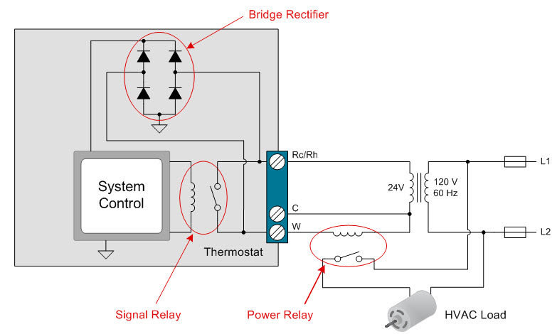
How To Power Your Thermostat Using Solid State Relays Industrial Technical Articles Ti E2e Support Forums

Variety of solid state relay wiring diagram.
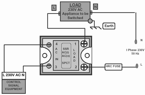
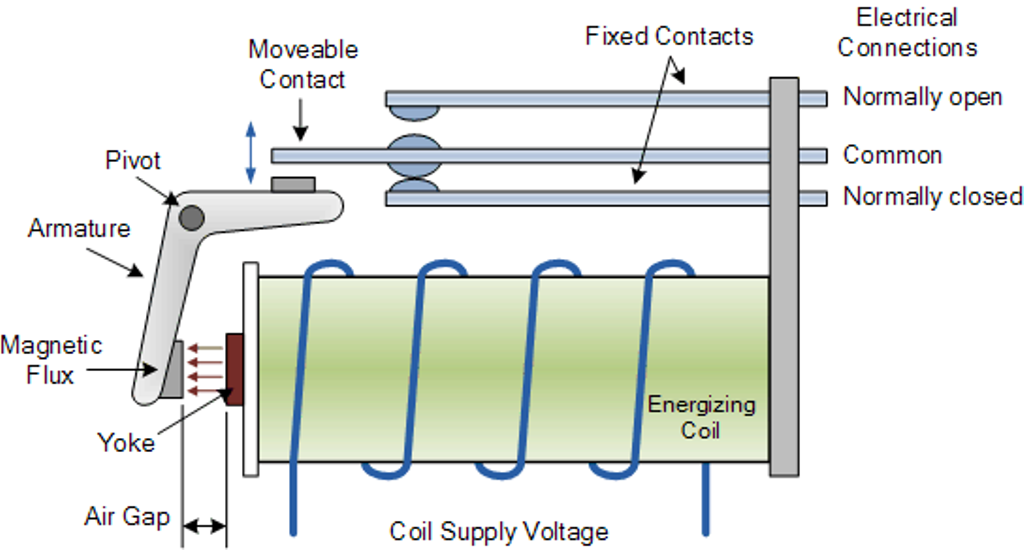
Heter osilate control solid state relay wiring diagram. The micro controller which is from 8051 family is intended to produce output pulses following zero voltage pulse to make sure that the load is getting turned on at zero cross of the delivered waveform. Diagrams will show how multiple relays one relay or another or just one relay can control your device. All examples shown are for spdt single pole double throw relays which includes any of the 5 10 or 20 amp relays on this site. Or contact our international customer service centre icsc.
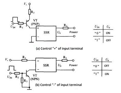
In this article we will briefly discuss the ssr solid state relay its construction operation schematics different types of ssr relays based on its switching property and input output forms we will also discuss the advantages disadvantages of solid state relay ssr comparing to electromagnetic. To solid state relays definition a solid state relay is an electronic component which performs an interface function with electrical isolation between a control circuit usually at low level and a power circuit connected to loads which may have high. What is solid state relay. Solid state relay project block diagram loads are coupled in sequence with a cluster of triacs being impelled by the opto isolator.
Solid state relay is a hybrid circuit normally composed of an optocoupler which isolates the input a trigger circuit that detects the zero crossing of the line current and a triac or similar device that acts as a circuit breaker. A wiring diagram is a simplified traditional pictorial depiction of an electrical circuit.

Heter Osilate Control Solid State Relay Wiring Diagram Wiring Diagram
Https Nuwaveproducts Com Manuals Ssrman 1p Cl Manual Pdf

Solid State Relay With 16a Scr Optical Trigger With Images Circuit Diagram Electronic Schematics Electronics Circuit

Dc Relays For Solar Panels

To 0512 Homebuilt Solid State Relay Circuit Board Component Layout Free Diagram

Introduction 1 2 Tca Explosive Tca E144 Type Of Furnace Belt Width Clearance Above The Belt Number Of Heating Zones Heated Length Explosive Ppt Download

Temperature Controllers Further Information Technical Guide Australia Omron Ia

Smart Data Logging Water Geyser Heating Controller For The Home 11 Steps With Pictures Instructables
Frequently Asked Questions Davies Craig

Water Heater Contactors
How To Use Relays To Control High Voltage Circuits With An Arduino Projects
How To Replace A Blower Fan Motor In Under 30 Minutes

Engineering Essentials Relays And Contactors Machine Design
