Maxon 3 Way Switch Wiring Diagram

Ibanez Maxon Sd9 Sonic Distortion With Images Distortion
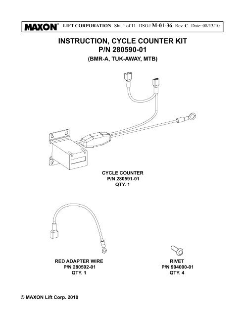
Instruction Cycle Counter Kit P N 280590 01 Maxon
Http Www Maxonlift Com Sites Default Files Docs M 16 21 Eo17185tp3 Operation Pdf
Https Www Maxonlift Com Sites Default Files 2017 04 M9725 Pdf
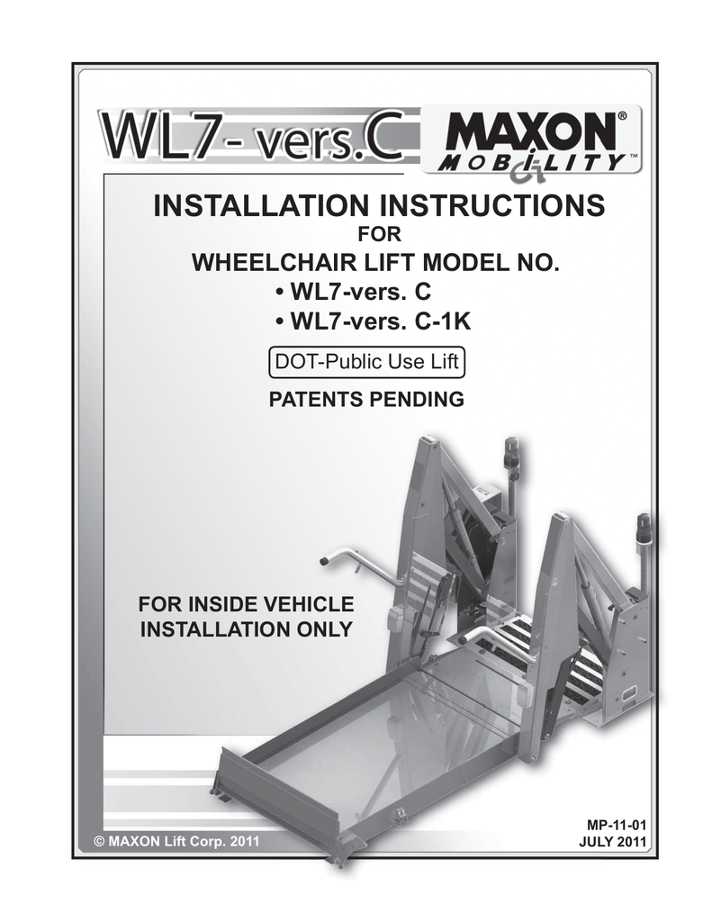
Maxon Wl7 Vers C Operator S Manual Manualzz

Maxon Gpt Series Liftgate By The Liftgate Parts Co Issuu

Typical 3 way switch wiring nm cable.
Maxon 3 way switch wiring diagram. Take a closer look at a 3 way switch wiring diagram. Traveler wires are interchangeable on each switch. It shows the parts of the circuit as simplified shapes and also the power as well as signal links in between the devices. The white wire of the cable going to the switch is attached to the black line in the fixture box using a wire nut.
Wiring diagrams for 3 way switches. Pick the diagram that is most like the scenario you are in and see if you can wire your switch. All three way switch and 2 way switch wiring diagrams have the same basic components. Interested in a 4 way switch wiring diagram.
Instruction gpt low voltage thermal switch lvts installation kit. Easy to read wiring diagrams for guitars basses with 2 humbuckers 3 way pickup selector switch. Components of 3 way switch wiring. This might seem intimidating but it does not have to be.
In the 1st diagram below a 2 wire nm cable supplies power from the panel to the first switch box. Refer to lvts wiring diagram on sheet 9. If you are trying to troubleshoot a 3 way switch operation then you will need to identify the function of each wire. If the liftgate is a gpt or 80 series open pump box cover.
The black line wire connects to the common terminal of the first 3 way switch. Options for north south coil tap series parallel more. 3 places white control switch wire motor cable lock washers 3 places hex nuts 3 places lvts jumper wire fused power cable motor cable starter solenoid starter solenoid connecting lvts to starter solenoid fig. 3 way switch diagram 2 above shows the electricity source starting at the fixture.
For an mtb liftgate remove 4 bolts lock washers flat washers and pump cover to gain access to power unit fig. 3 of 10 dsg m 01 29 rev. A wiring diagram is a simplified conventional photographic depiction of an electrical circuit. With these diagrams below it will take the guess work out of wiring.
Collection of 3 way motion sensor switch wiring diagram. Wires consisting of a line a load a neutral a pair of travelers and two 3 way switches.

State Of The Stomp Maxon S Susumu Tamura Interview Cool Guitar

Your Guide To Maxon Liftgate Parts And New Gates Liftgateme

Your Maxon Liftgate Switch Guide Tagged Maxon Liftgate 72 25

Pin On Arduino
Router Switch Configuration Using Packet Tracer Gns3 In 2020

Maxon 80 Series Tuckaway Liftgate Parts Manual By The Liftgate

Maxon 50431 Adjustable Orifice 3 8 Npt

Maxon 72 150 Te 20 Liftgate Parts Manual By The Liftgate Parts

Image Result For Diagram Of Chevrolet 4l60e Transmission Rebuilt
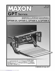
Maxon Gptwr 25 Installation Manuals Pdf Download Manualslib
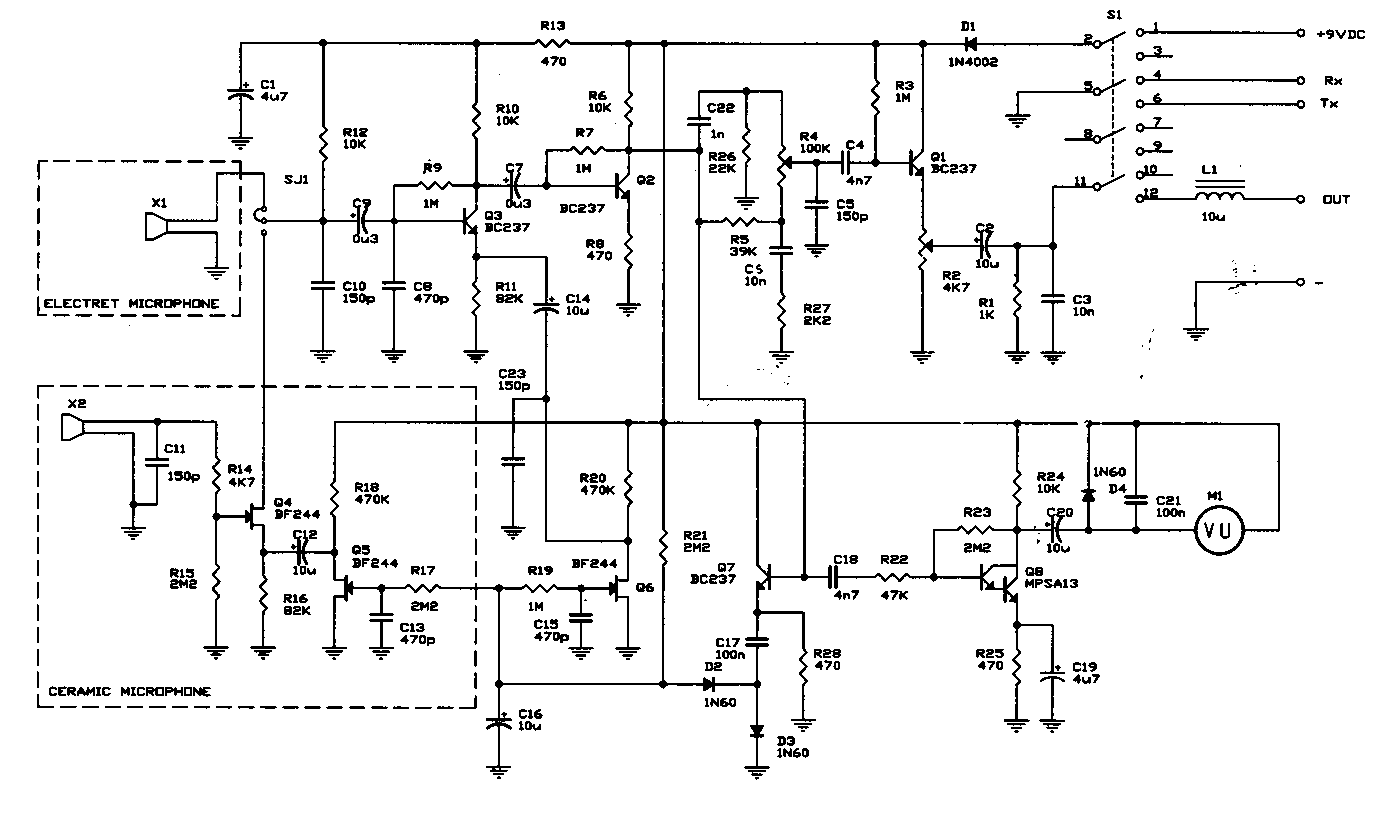
7757b Maxon Cb Mic Wiring Diagrams Wiring Resources
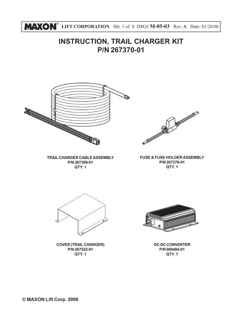
Instruction Trail Charger Kit P N 267370 01 Maxon

Pin Di Gitar
