Maxon Valve Wiring Diagram
Https Esys Us Pdf Maxon 6400series Installation Pdf

Rv Plumbing Diagram Google Search Bathroom Layout Airstream
Https De Maxoncorp Com Clientuploads Pdf English E Oil Electro Mechanical Valves Specs Oil Valves Pdf

Rv Plumbing Diagram Google Search With Images Water Systems

Wobbletron Sabrotone With Images Diy Guitar Pedal Guitar

Wood Stove Hot Water Google Search Hot Water
Find info for liftgate service and sales.
Maxon valve wiring diagram. 3 of 10 dsg m 01 29 rev. Maxon liftgate wiring schematic. There s a maxon liftgate for every job find the perfect one for your specific needs right here. This unwavering dedication to safety and reliability is the reason most shut off valves are called maxon valves the grey and yellow valve that proudly protects the world s heating equipment at the lowest cost of.
Maxon liftgate switch wiring diagram bypass liftgate ajar switch 3 along with tommy liftgate wiring diagram together with wire diagram lift gate pumps in addition honeywell zone valves wiring diagram along with maxon wire diagram as well as anthony lift gate wiring diagram also lift gate harness with coiled wire also maxon hydraulic. By listening to the valve cycle to its energized state you can detect if any of these critical electrical components needs to be replaced. The pump and motor unit for this lift can require up to 205 amps of electrical power at 12 volts. If the liftgate is a gpt or 80 series open pump box cover.
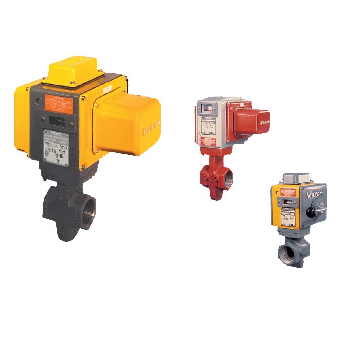
All shut off valves come equipped with maxon s long lasting metal to metal seating. Each maxon automatic reset shutoff valve comes with three critical electrical components solenoid motor position switch that need to work together for the valve to operate properly. For an mtb liftgate remove 4 bolts lock washers flat washers and pump cover to gain access to power unit fig. These electrically actuated valves shut off gas or oil lines in less than one second.
Wire the valve in accordance with all applicable codes and standards. A variety of optional body materials and body connections provide reliable operation even for highly corrosive fuels and for oxygen. Supply voltages must agree with valve s nameplate voltage within 15 10 ac or dc for proper operation. Since the 1920 s maxon has been the primary innovator of safer more durable shut off valves and control valves for industry.
For electrical wiring schematics refer to appropriate maxon catalog literature and or the wiring schematic diagram affixed inside your valve s access cover.

Gas Water Heater Diagram Google Search Water Heater Water

Pearl Vorg Warp Sound Synthesizer Diy Distortion Pedal Diy

Pin By Garth Wilden On Music With Images Guitar Distortion

How To Install Electric Heating Element Hot Water Google Search

Maxon Columnlift Bmr A Sn 1098xx 0303xx Wiring 2 Pump Gravity

Devin Townsend Live Tube Rig Music Machine Rigs Guitar

Pin Em Schematic And Pcb Layout

Gravity Hot Water Google Search With Images Water Heating

Fx50b Png 770 513 Pixels Circuit Guitar Effects Guitar Amp

Hmp Light Ver 5 Gif Light Heavy Metal Gif

Pedalshield Uno Assembly Kit This Is A Kit To Assemble

Pin On Hagstrom Wiring

Solenoid Valve Energized Or De Energized State With Images