Maxxforce Dt Wiring Diagram

Navistar Maxxforce Dt 9 10 Hd Obd 2013 Wiring Diagrams Auto

Maxxforce 7 Vehicles Mechanical Engineering

Maxxforce Dt 9 10 2010 2013 Oil Separator Speed Sensor

Zh 9968 Maxxforce Dt Wiring Diagram Free Diagram
Wiring Diagram 2011 International Durastar Wiring Diagram

International Maxxforce Diagrama Naturaleza Energia Y Recursos
28 2007 electrical circuit diagrams.
Maxxforce dt wiring diagram. Diagnostic service manuals. The fuel strainer can be seen when the pump is removed from the filter module. 2010 maxxforce fi dt 9 and 10 engine diagnostic manual navistarfi n9 n10 diagnostic manual description epa 2010 and later dt 9 10 engines use a fuel module that incorporates many features including an electric fuel pump fuel heater and fuel strainer. Maxxforce 5 maxxforce 7 maxxforce 11 13 maxxforce dt 9 10 maxxforce 15 navistar n9 n10 n13 aftertreatment troubleshooting press thanks rep pm for pass mhh auto.
Remote radio n amp and n wired remote and n driver interface display. Odometer powers up but cluster gauges don t cycle and are dead. 0000002441 paystar series with maxxforce 11 13 15l n13 or isx15 engines supersedes s08352. Wont crank from key.
Lonestar and prostar chassis built january 2007 and after electrical circuit diagrams iii 4 44. 0000017581 electrical circuit diagram manual electrical circuit diagrams 3200 4100 4200 4300 4400 7300 7400 7500 8500 8600 supersedes s082854. Eged 525 1 engine wiring diagram form maxxforce 15 beginning with 2011 model year pdf eged 530 3 performance diagnostics maxxforce 11 13 epa 2010 pdf eged 535 2 performance diagnostics maxxforce 15 beginning with 2011 model year pdf eges 415 2 maxxforce 11 and 13 engine service manual 2011 pdf. 3200 4100 4200 4300 4400 7300 7400 7500 7600 7700 8500 8600 mxt rxt models built oct.
Hello i need a wiring schematic for a 2011 maxxforce 7 on a 2011 navistar ic uc school bus. Maxxforce dt 9 10 wiring diagram. 0000003601 2011 2015 ic bus be ce series electrical circuit diagrams supersedes s08377. Maxxforce dt 9 10 wiring diagram free download as pdf file pdf or read online for free.
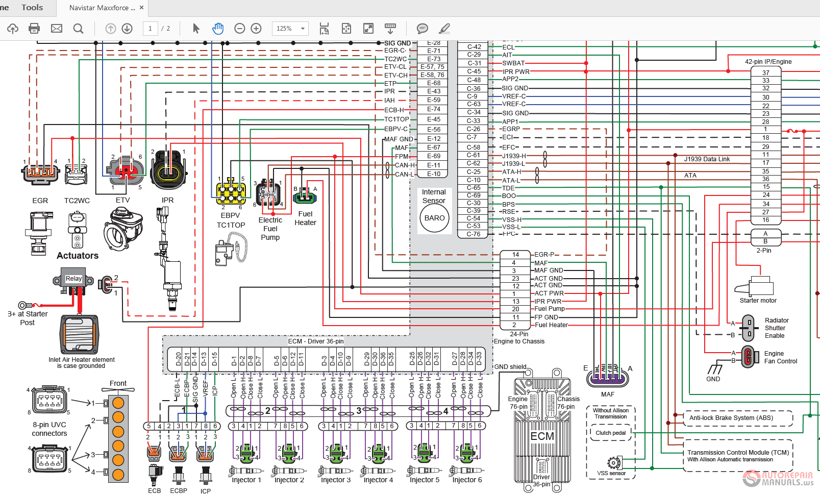
Maxxforce dt 9 10 2010 2013 engine wiring diagram page 2 of 3 86 pin connector 6341 53 pin connector 6340 twisted pair red b battery voltage red high side driver control blue vref 5 volts green green a c speed signal signal brown data communication black black purple injectors gnd ground low side driver control color code for schematic lines.

I Need Pin Out For 1 Ecm On Dt466 Engine In

International Truck Isis 2015 Service Information Solution

2012 International Maxxforce Dt Wiring Diagram Maxxforce Dt

International Maxxforce Diagrama Diagrama De Circuito Electrico

6 Pin Cdi Wiring Diagram Lukaszmira Com At Roc Grp Org And With

Related Image Diagrama De Circuito Electrico Camiones

Awesome Ddec V Wiring Diagram Contemporary Electrical Circuit And

Detroit Diesel Series 60 Ecm Wiring Diagram 5a20df51db79d To

20 Simple Automotive Wiring Diagrams References Electrical

Related Image Powerstroke Ford Diesel Powerstroke Diesel

Detroit Series 60 Ecm Wiring Diagram Dolgular Of Ddec V Ecm Wiring

13 Furthermore Caterpillar C12 Engine Diagram Pictures Wiring

Pin On Auto Electrical
